Centre de Biochimie Structurale
Faculte de Pharmacie
15, av Charles Flahaut
34000 MONTPELLIER
Tel: +33 (0)4-67-04-38-47
email: catrino@cbs.cnrs.fr
ViTO is a tool that is useful for:

As previously mentionned, the original aim was to facilitate the tedious work of refining the alignment of a target sequence onto a template structure. This step is crucial for homology modelling because no comparative modelling program can recover from an alignment error. Usually, an initial sequence/structure alignment is obtained from a threader or from other automatic methods (e.g. Psi-BLAST). These automatic methods are more tuned to detect the relationship between a given sequence and known structures rather than to produce exact alignments. As a consequence, expect for highly homologous sequences you can not rely on the given alignment for homology modelling. Optimizing an alignment is a long repetitive process which require to test many different alignment hypotheses which can be summarized as:
Using ViTO, you immediatly locate where insertions and deletions fall in the template structures. It makes it easy to detect errors like indels in helix and/or strands which are more unlikely to happen than indels in coil regions. At any time, you can compute a threading energy for the alignment. The lower the energy, the better the alignment. The threading potential used is a pairwise Potential of Mean Force (PMF) using pseudo-CB as interaction centers (for a complete description see Bryant & Lawrence).
At any time, you can append a new alignment to the existing one and/or insert a new protein structure. ViTO supports multi-chain alignments (i.e. multimeric proteins / protein complexes) which is a seldom feature among alignment editors. ViTO can input PDB files containing exotic amino-acids, DNA/RNA and hetero atoms and load only parts of a structure. When the structure is read, the user is asked to select with the mouse the parts of interest. This is helpful when studying SH3 domains for example and loading the portion of a protein containing a SH3 domain among others. This feature is unique to ViTO.
As the project went on, new features were added icluding tools to analyse variable regions in proteins, locating mutational hot spots. In a way, ViTO is a tool for doing 3D-phylogenic analysis on the fly and in real-time. These features of ViTO are presented in the 2 first examples of the tutorial.
ViTO might also be used as a structure renderer only, but the 3D renderer is a bit crude compared to other programs like Rasmol, PyMOL and others which are dedicated to this task.
ViTO is launched using:
vito [-ali my_ali.ali]use the -ali option to load the given alignment on startup. ViTO can read severali alignment formats, the format being guessed from the file extension.
ViTO was built in order to work in conjunction with MODELLER which use PIR alignments. As a consequence, the PIR alignment format is the preferred one (and ViTO only saves alignments in PIR format). Some fancy things are performed when reading a PIR alignments, for example structures are automatically loaded if the PIR file contains some extra infos. This feature is disabled with other alignment formats. As an example, let's consider the following PIR alignment:
>P1;1edo
structureX:/DATABASE/PDB/pdb1edo.ent.Z:@:A:X:A: : :2.30:-1.00
SPVVVVTGASRGIGKAIALSLGKAGCKVL-VN--------Y-ARSA-KAAEEV-------SKQI-EAY-G-GQ--AIT-F
G--GDVSKEADVEAMMKTA---IDA---WG-TIDVVVNNAGITR-DTLLIRMKKSQWDEVIDLNLTGVF-LCT-QA-A-T
-KIMMKKRK-GRIINIASVVG-LIGNIGQANYAAAKAGVIGFSKTAAREGASRNINVNVVCPGFIASDMT--AKL-GED-
ME-K--K--ILGTIPLGRTGQPENVAGLVEFLALSPAASY----ITGQAFTIDGGIAI*

>P1;FABG_ARATH
sequence
SPVVVITGASRGIGKAIALALGKAGCKVL-VN--------Y-ARSA-KEAEEV-------AKQI-EEY-G-GQ--AIT-F
G--GDVSKATDVDAMMKTA---LDK---WG-TIDVVVNNAGITR-DTLLIRMKQSQWDEVIALNLTGVF-LCT-QA-A-V
-KIMMKKKR-GRIINISSVVG-LIGNIGQANYTATKGGVISFSETPAREGASRNINVNVVCPGFIASDMT--AEL-GED-
ME-K--K--ILGTIPLGRYGKAEEVAGLVEFLALSPAASY----ITGQAFTIDGGIAI*
This file contains 2 sequences, the first one being the sequence of chain A of the PDB structure 1edo. When ViTO reads this file, it automatically reads the structure 1edo from the file /DATABASE/PDB/pdb1edo.ent.Z and displays it in the 3D window. The segment to read is guessed from the given bounds :
For a complete desciption of this, please report to the MODELLER documentation which can be accessed at http://guitar.rockefeller.edu/modeller/manual/manual.html.
The following sections describes the menus and windows of ViTO and how to interact with them.
The menubar contains the following menus:
Here is a snapshot of the window
this window has 3 parts:
Mouse movements
In the name panel
In the sequence panel
Shortcuts & hot keys
In the name panel
In the sequence panel
Proteins and other molecules are displayed in this window. It is a basic structure renderer. It is driven via the "display menu". This menu is a tearoff menu (the first entry is a dashed line). The best thing to do is to tear this menu off on startup, it makes it easier to access its functions.
Mouse movements
Shortcuts & hot keys
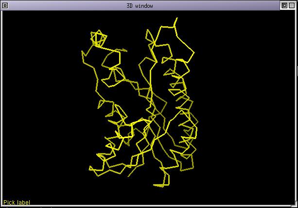
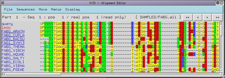
FABGs are a family of enzymes performing redox reactions on various substrates using NADP as a cofactor. In the SAMPLES directory of ViTO there is an alignment called FABG.ali, launch ViTO and load this alignment. Here are snapshots of what you should get.
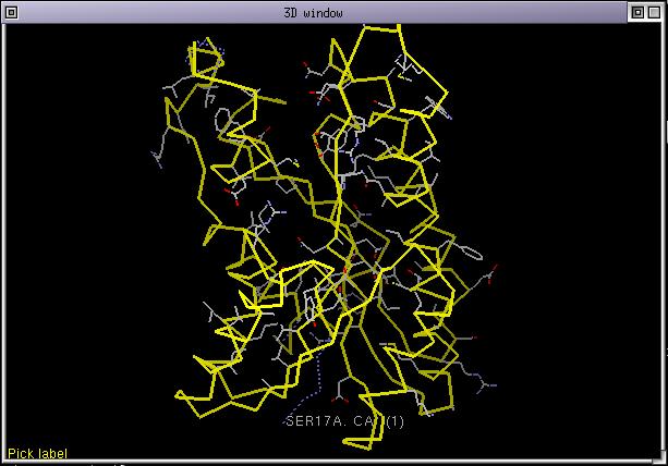
The structure 1edo is rendered with its CA trace in yellow. This is the default rendering when a structure is loaded directily from an alignment. In fact the structure is colored according to the alignment but the colorization list is still empty so the structure is colored as if it was aligned against itself. Select 1edo and display its sidechains (menu Display/toggle sidechain display)
Now, try to pick amino acids either in the 3D window or in the alignment window. As you can see the 2 windows are connected. You can also try using directional arrows in both windows.
Now select the sequences as in the next snapshot
and run the menu command Manip/Set colorization list. Immediatly the 3D display is updated and 1edo now has less sidechains displayed and some parts of its CA trace are displayed as dashed yellow or blue lines.
Dashed blue lines means that there was a deletion in the structure and yellow dashed lines an insertion. You can directly go to insertions and deletions by picking the corresponding CAs in the 3D window. The sidechains which are still displayed correspond to amino acids which are identical through the whole colorization list. As the number of sequences in the colorization list increase, the number of displayed sidechains will decrease. As you can see conserved sidechains are mostly gathered in a region of 1edo. This is not by chance, this region correspond to the NADP binding pocket.
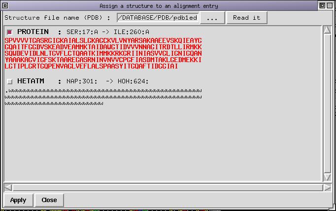
The 1edo structure has been solved in complex with NADP. It is now time to use the interactive structure loader. Run the menu command File/Insert PDB structure, the following dialog box appear:
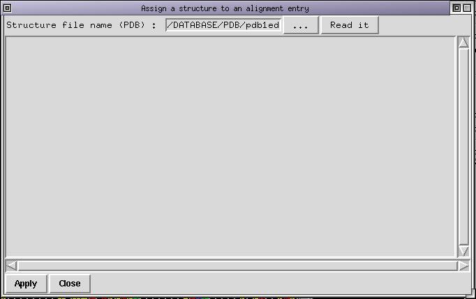
Use the "..." button to look for the file "pdb1edo.ent.Z" which lies in the SAMPLES directory. Once done click on the "read it" button to load the structure in memory. By default the first chain is selected, which is indicated by the color of the sequence (displayed in red bold). The dialog box looks like this :
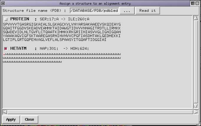
You don't want to load the protein chain but the ligand. You need to deselect the first chain which is done by clicking on the corresponding checkbutton. Next step consists to select the checkbutton for the other chain. Once done you can select with the mouse (with Left Button pressed) the first residue in the chain. It is marked as a '.' and correspond to NADP. Do not select the following water molecules indicated with 'w'. With the middle button pressed you can deselect things you do not need. If you succeeded, the dialog box should now look like:
Now press the "Apply" button to insert the selected part of the structure in the alignment. A new sequence named '1edo_0' is appended to the end of the alignment (its name is displayed in red because it is atructure) and the NADP molecule is displayed in its pocket. As you can now check, most of the conserved sidechains are in contact with NADP making it clear that the alignment is probably not bad. In fact, this alignment was obtained from BLAST and was refined with ViTO to correct for small bugs.
Another way to check the alignment is to compute the threading energy. First deselect all sequences (Button-3 in the name panel) and select the 1edo sequence. Run the menu command Manip/Set threading list, this will set the treading list to contain just the structure 1edo. Now run the menu command "Manip/Threading". A new window has been opened and looks like:
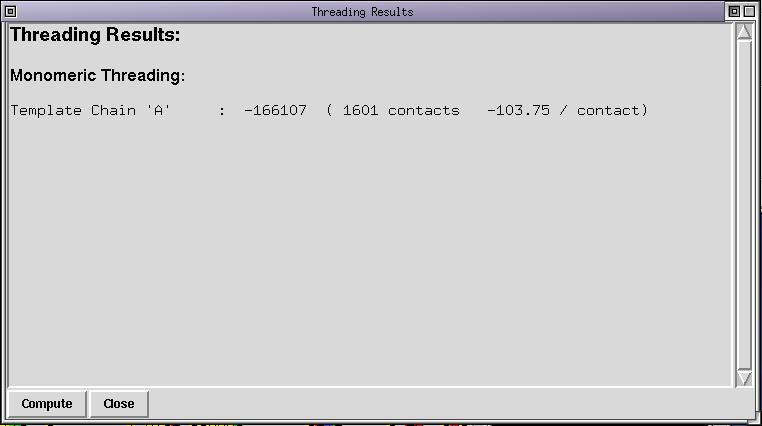
The threading energy computed correspond to the energy of the structure threaded onto itself. As you can see the energy is low (very negative) and the average energy per contact is low too. This is typical of self-threading. By the way, positive threading energies always mean that there is an alignment error or that the selected template is not good. Now select 1edo and FABG_ARATH and run the menu command Manip/Set threading list. The threading list now contains 2 sequences, compute the threading energy again, either via the "Compute" button in the threading dialog box or via the menu. The contents of the threading dialog box is updated :
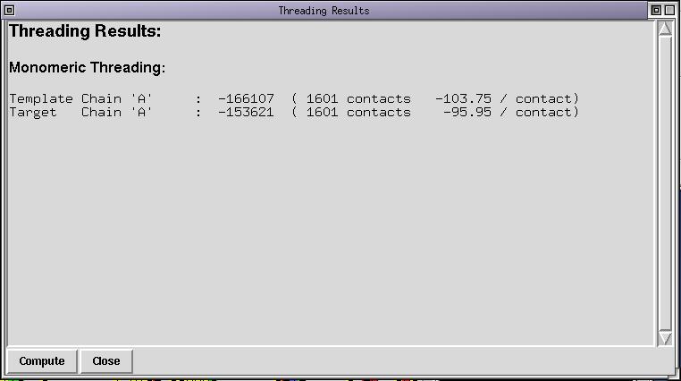
As you can see, the energy of the target (FABG_ARATH) is almost as good as the self threading energy of 1edo. This means that 1edo is a valid structural template for compartive modelling of FABG_ARATH and that the alignment is correct. You can alter the alignment between FABG_ARATH and 1edo and compute the threading energy again. You can notice that the threading energy is never as good as it initially was. As you can see too, the 3D display is updated because FABG_ARATH belongs to the colorization list. Now revert to the original alignment by undoing your changes.
You can modify the threading list to contain more sequences. The target threading energy is now the average of the threading energy of each sequence in the list. The threading list must contain one and only one structural template. The self-threading energy is always computed because you need to compare the target threading energy to the template one to decide whether the alignment is correct or not. The self-threading energy is not always as low as for this example and just computing the target threading energy can lead to errors.
The last step for this example will present the shading functions "shade by id rate" and "shade by entropy". These functions provide a simple way to do crude phylogenic analysis on a protein family. Of course this is not fancy phylogenic analysis but as all phylogenic methods rely on a given alignment it is better to get the right one before doing anything. ViTO proves to be useful for this.
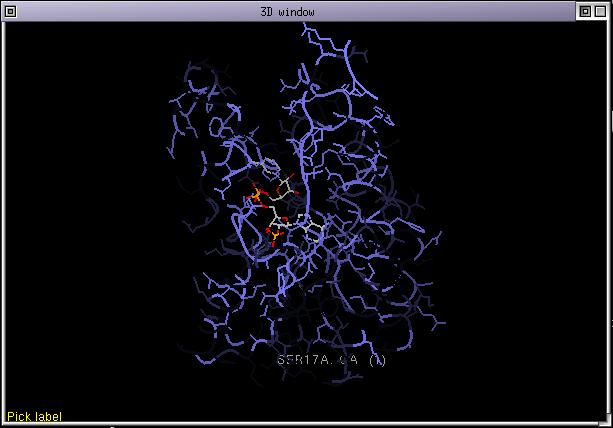
Run the menu command Display/Customize id rates and select a linear ramp. The linear ramp fills the id rates table like this:
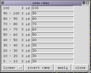
It means that the color for residues conserved in the colorization list will have their color unchanged. Those 90 % will have their color with 90 % of its natural intensity and so on... Deselect all selected sequences if any and select 1edo. Color it by CPK then click on "shade by id rates". The 3D display is updated and some parts of the proteins (those less conserved with respect to the structure 1edo) are shaded. If you click again on "shade by id rates", the highly conserved parts become almost the only one visible. The effect is cumulative. If you want, you can now color 1edo by structure and start again clicking 3 time on the "shade by id rates" button. The resulting picture looks like:
The "shade by entropy" function acts the same except that the amino acid seen in the structure is not taken as a reference but the most conserved one instead. It does not give exactly the same results because sometimes the residue at a position in a structure is not representative of the family. This functions seems more clever than the previous one but we decided to keep both.
In this example, we will study the case of a rice virus that damage cultures around the world. A lot of strains from different regions have been collected and the sequence of the capsid protein vary in a few positions from strain to strain. The sequences have been classified in 6 families, and let's imagine there are monoclonal antibodies that can be used to make the distinction between the different families. Imagine that your goal is to determine which amino acids are accessible to the antibodies and to highlight the difference between the families that can explain the antibodies' specificity. We won't solve the whole problem but we will just do a few steps.
This example will show you how ViTO works with multi-chain alignments and how the use of the "shade by entropy" function can make it easy to pick up mutational spots on the protein surface.
Launch ViTO and load the alignment "cp3.pir" which is in the SAMPLES directory. Once started, a trimer should appear in the 3D window. This trimer consists of 3 identical subunits. Here is a snapshot of the screen.
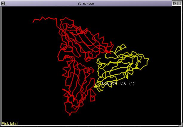
You can navigate from one chain to the other in the alignment with the buttons at the right of the status bar or directly pick a position on the screen. Select all the sequences whose name end with "_S5" or "_S6" and set the colorization list. Color the structure by chain and show its sidechains. Now customize the id rates table as this:
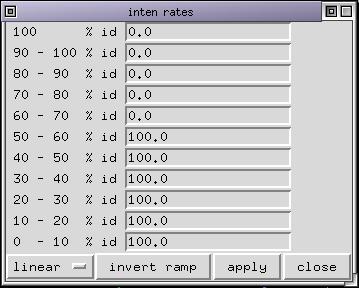
What does it mean ??
Only those residues that are least conserved are displayed. This helps to locate where sequences from the strain "S5" differ from those of strain "S6". Some mutations appear in buried parts of the protein and are not accessible to the antibodies. Other mutations are on the solvent exposed surface of the protein and they might explain why a certain antibody make a distinction between the 2 strains.
You can go on and study variations within a strain or between other strains... For example if you select all the sequences whose name end with "_S1" (strain 1) and set the colorization list with this selection. Next color the structure by chain and shade by entropy, you should have nothing displayed. If you change the id rates you can point out some variations in sequences in the strain 1 but almost none of these mutations appear in the solvent exposed part.
We do not pretend that hypothetical problem we imagine will be solved in a few minutes but it might give some clue about what's going on.
As mentionned in the first section of this manual, the aim of ViTO was to ease the alignment of sequences onto structure for comparative modelling. In this section, you will load an alignment produced by a threader and modify it until you're satisfied. At the end you will prepare the MODELLER input files from ViTO. You will load the models that MODELLER computed and identify the ill-modelled portions.
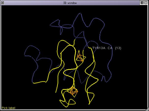
Launch ViTO and load the alignment "initial.pir" from the SAMPLES directory. This alignment has been produced by a threader. The query is a ferredoxin protein. Its structure has been solved but we pretended that we didn't know that. We submitted the query to our server https://bioserv.cbs.cnrs.fr dedicated to fold recognition and homology modelling.
Once the alignment is loaded the CA trace of 7fd1 is displayed. Set 1fdx as the colorization list. Immediatly the insertions/deletions are displayed. Assuming you're in stereo mode and you displayed 7fd1 as ribbons and not its CA trace, you should obtain this:

It is easy to see that there are several problems with this alignment.
For the first anomaly mentionned, the best thing to do is to suppress the deletion. For the second anomaly it is easy to reduce the gap length. Once done the alignment should be:
>P1;1fdx
sequence
AYVINDSCIACG--ACKPECPVNIIQGS--IYAIDADSCIDCGSCASVCPVGAPNPED----------------------
--------------------------*
>P1;7FD1
structureX:/DATABASE/PDB/pdb7fd1.ent.Z:1:A:106:A:::1.30
AFVVTDNCIKCKYTDCVEVCPVDCFYEGPNFLVIHPDECIDCALCEPECPAQAIFSEDEVPEDMQEFIQLNAELAEVWPN
ITEKKDPLPDAEDWDGVKGKLQHLER*
The initial alignment was:
>P1;1fdx
sequence
AYVINDSCIACG--ACKPECPVNIIQGSI--YAIDADSCIDCGSCASVCPVGAP------
------------------------------------------NPED*
>P1;7FD1
structureX:/DATABASE/PDB/pdb7fd1.ent.Z:1:A:106:A:::1.30
AFVVTDNCIKCKYTDCVEVCPVDCFYEGPNFLVIHPDECIDCALCEPECPAQAIFSEDEV
PEDMQEFIQLNAELAEVWPNITEKKDPLPDAEDWDGVKGKLQHLER*
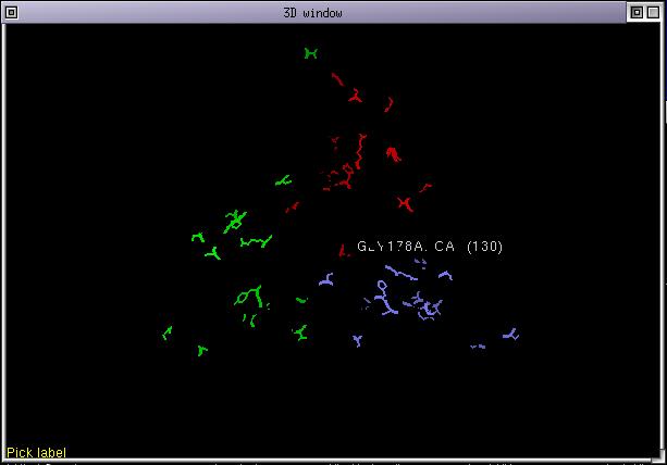
Now we need to check the last anomaly mentionned. We will do it by inspecting the amino acids in contact with the 2 iron-sulphur centers in 7fd1. Remember that we are studying a ferredoxin protein. To do this, use the interactive structure loader to fetch the 2 iron-sulphur centers from the PDB file 7fd1. Once done, the 3D display looks like:

As you can see, the deletion between 12-th and 15-th is located close one of the iron-sulphur center, there are interactions between the backbone amide nitrogen of residues between 12-15 with the iron-sulphur center. It can also be noticed that the CYS 11 sidechain in 7fd1 does not contact the iron-sulphur center (others cysteine residues do), consequence is that it is not mandatory to align this cysteine with another one. This leads to the following alignment.
>P1;1fdx
sequence
AYVINDSCI--ACGACKPECPVNIIQGS--IYAIDADSCIDCGSCASVCPVGAPNPED----------------------
--------------------------*
>P1;7FD1
structureX:/DATABASE/PDB/pdb7fd1.ent.Z:1:A:106:A:::1.30
AFVVTDNCIKCKYTDCVEVCPVDCFYEGPNFLVIHPDECIDCALCEPECPAQAIFSEDEVPEDMQEFIQLNAELAEVWPN
ITEKKDPLPDAEDWDGVKGKLQHLER*
>P1;7fd1
structure:7fd1:107:A:108:A::::
..------------------------------------------------------------------------------
--------------------------*
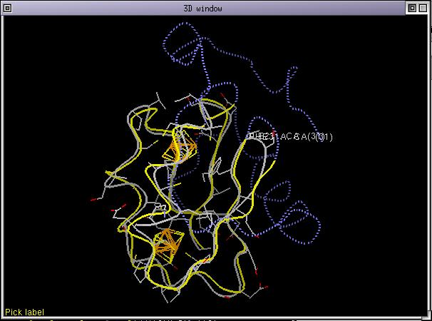
and the corresponding 3D display:
As you can see, ViTO greetly helped to correct the 3 mistakes that were hidden in the initial alignment. Now let's cheat a little bit and load the structure of 1fdx with the interactive structure loader. Load the whole structure including iron-sulphur centers. Align the protein chain of the loaded structure onto 1fdx, set its rendering mode to CPK. Selects the 2 structures 1fdx_0 and 7FD1 in the alignment and run the menu command Manip/Fit selected seqs. The 2 structures are superposed according to the alignment and you should now have you 3D window looking like:
You can now check the structural alignment by moving the cursor in the alignment. The labels displayed for both structures (7FD1 and 1fdx_0) should be almost superposed. If it is the case it means that the aignment is correct, if there were a shift between the positions of the 2 labels, it would mean that there were an alignment error. You can perform a threading computation if you wish.
Let's revert just before the verification. Run the menu command File/Open alignment... and choose the file second_step.pir from the SAMPLES directory. Now select the sequence 7FD1 and 1fdx and run the menu command File/Write MODELLER File.... You will be asked to choose a file name to save the MODELLER script to (remember that MODELLER scripts must have a '.top' extension). Now, you are free to run this script from any terminal window.
Let's suppose that you've succesfully run the MODELLER script. We will now load the models into ViTO and inspect them. Use the interactive structure loader to load the 2 files "mod_1fdx_1.pdb" and "mod_1fdx_2.pdb" from the SAMPLES directory. Align their sequence with the one of 1fdx and superpose these 2 structures with 7FD1. If you color these structures by temperature, you will see the ill-modelled portions in red. MODELLER uses the B-factor to store a score about how good an atom is modelled. In this case, nothing appears in red because MODELLER thought he made a good job. You can check that sidechains of cysteine residues contacting the iron-sulphur centers are not always well modelled, they do not contact the iron atom any more. It happened beacause we didn't included special restraints for these residues, so the story does not end here...
ViTO preferences are stored in an ASCII file called "vito_settings.prm". There is one template file in the distribution. Upon startup, the program tries to find a file of that name in the user's home directory, if it fails it loads the default file. Before customizing ViTO you need to make a copy of "vito_settings.prm" in you home directory (say /home/you) and edit it with your favorite text editor. If you edit the default file the changes will apply to all users that have not their own "vito_settings.prm" file.
This file contains just a few lines. it should be self-explanatory but here are some other explanations about each option:
For the moment, there is no way to read preferences on the fly. ViTO must be started again to have preferences taken into account. This will be fixed in a near future.
ViTO is distributed as binaries and is free of charge. ViTO runs under LINUX, IRIX 6.3 and above and under Windows 98 and later. To install ViTO download the gziped tar file corresponding to your platform. Unpack it and follow the instructions in the README file.
We do not ask any money for ViTO unless you insist, but we would like that you cite it when you used it for a paper. It it also recommended that you write an e-mail to the author with the subject "New VITO user" with your name, address, company, phone number and e-mail. This will help us to keep track of the users and to send you an e-mail when a new version will be available.
ViTO is an ongoing project and is still under development, we are sure it is not bug free sor I will be glad if you send bug reports, comments and suggestions. Here are some functionality that we plan to add in a near future:
This section is for people interested in software development.
ViTO has been developped in C, using TCL/Tk and [iTCl/Itk] for the user interface. The 3D renderer has been developped with OpenGL using the portable glut library from M.Kilgard. This library has been modified in order to be used in conjunction with TCL (modification of the event loop). It allows to use glut without modification but to add Tk widgets to the program. I can provide the source code for this tkglut library.